Integrating 3D-FEA

In recent years, several programs for the design of machine elements in gear boxes like shafts, gears and bearings have seen the addition of 3D-FEA calculations. This article deals with 3D-FEA calculations, their usefulness and the features that should be supported.
Integrating 3D-FEA
In recent years, several programs for the design of machine elements in gear boxes like shafts, gears and bearings have seen the addition of 3D-FEA calculations. This article deals with 3D-FEA calculations, their usefulness and the features that should be supported
Software programmes for the design of machine elements focus mainly on analytical methods for assessing the strength of shafts, gears or bearings. Shaft calculations often use nominal stresses and notch factors, and standards like DIN 743 or other analytical methods are used. For gear strength, analytical assessment methods like ISO 6336 or AGMA 2001 are used, while for bearings a life calculation according to ISO 281 or ISO/TS 16281 is used. These methods are reliable for standard cases; they are fast and have been used for a long time.
WHAT IS 3D-FEA?
Finite Element Analysis (FEA) is the use of calculations, models and simulations to predict and understand how an object might behave under various physical conditions. FEA calculations use the finite element method (FEM), a numerical technique that cuts the structure of a 3D object into several pieces, or elements, and then reconnects the elements at points called nodes. The FEM creates a set of algebraic equations which engineers, developers and other designers can use to perform FEA.
Using FEA can reduce the number of physical prototypes created while also optimising all components during the design phase, providing the safe simulation of potentially dangerous or destructive load conditions and failure modes.
WHY THE NEED FOR 3D-FEA?
The first point to mention is the improved consideration of stiffness. The housing stiffness will affect the displacement of the shafts. This will affect the contact pattern of gears and the tilting angle of bearings. For standard industrial gearboxes, housings are usually stiff, with minor influence. But for automotive gearboxes, wind turbines or other applications with optimisation for weight, the influence might be important to consider. The face load factor for gears according to methods A and B of ISO 6336 requires the consideration of deformations of housings and gear bodies, possibly calculated based on 3D-FEA.
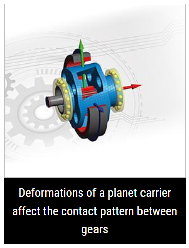
Planet carriers will deform under torsion. This deformation will also affect the contact pattern of gears and a simple cylindrical shaft model for the carrier might not be sufficient.
If the thickness of housings around bearing seats is small and varies around the circumference, this can also affect the load distribution in bearings and therefore the reference rating life according to ISO/TS 16281.
Some programs simply import a reduced stiffness matrix for housings or other elastic parts like planet carriers. Basic items like different orientations of coordinate systems can quickly lead to errors. In addition, the deformation of the housing cannot be evaluated. It is less error prone if the geometry of the housing and its deformation can be evaluated together with the system - this also helps to understand the deformed states.
Thermal elongations regarding the preload of bearings must also be considered. Often only uniform temperatures are considered, which is preferable to no thermal expansion. Some programmes can also support non-uniform thermal states. In case of 3D-FEA calculations of high-speed rotating parts, the consideration of centrifugal expansion could be helpful, too.
Another use case of 3D-FEA can be improved stresses compared to analytical methods. Examples would be the influence of two notch effects being close to each other, like a shaft shoulder combined with a keyway or simply the strength assessment of housings or planet carriers. As the FEA-meshes are often designed for the evaluation of stiffness, they might be too coarse for a proper strength assessment. In this case, a full FEA program might be the better choice. However, stresses available in a programme for machine element calculations can serve as a first estimate.
FEA is commonly used in mechanical, aerospace, automotive and civil engineering applications, as well as biomechanics.
1.The news above mentioned with detailed source are from internet.We are trying our best to assure they are accurate ,timely and safe so as to let bearing users and sellers read more related info.However, it doesn't mean we agree with any point of view referred in above contents and we are not responsible for the authenticity. If you want to publish the news,please note the source and you will be legally responsible for the news published.
2.All news edited and translated by us are specially noted the source"CBCC".
3.For investors,please be cautious for all news.We don't bear any damage brought by late and inaccurate news.
4.If the news we published involves copyright of yours,just let us know.
Next Bearings from NKE Austria for railway traction motors and gearboxes
BRIEF INTRODUCTION
Cnbearing is the No.1 bearing inquiry system and information service in China, dedicated to helping all bearing users and sellers throughout the world.
Cnbearing is supported by China National Bearing Industry Association, whose operation online is charged by China Bearing Unisun Tech. Co., Ltd.
China Bearing Unisun Tech. Co., Ltd owns all the rights. Since 2000, over 3,000 companies have been registered and enjoyed the company' s complete skillful service, which ranking many aspects in bearing industry at home and abroad with the most authority practical devices in China.


